

How To Repair In Ground Freeze Proof Hydrant
Yard Hydrants are Frost-gratis and are great for getting water to remote locations that need it year round. In this weblog, we are going to get over some of the common adjustment and repair procedures.
If you take any further questions about these instructions, contact our Technical Support Team.
The Mutual problems / adjustments that we will address are:
- Thou Hydrant volition non Shut-off Completely
- K Hydrant is Leaking at the Stem Packing
- Replacement of One thousand Hydrant Head
- Replacement of G Hydrant Plunger
Chiliad Hydrant will non Shut-off Completely
Over time the condom plunger will wear and it may be necessary to arrange the hydrant. While it is rare that a new hydrant will leak, at that place is from time to time a case where the hydrant will lose it'due south manufactory setting. In that location is not need to panic the hydrant is non defective!
If the hydrant will not shut off completely, there are a few simple steps to suit the hydrant linkage to it'due south proper closing position.
Step 1
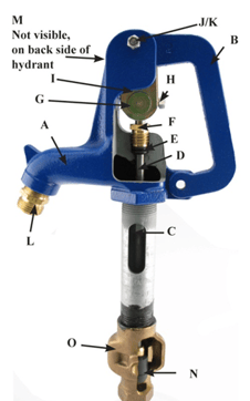
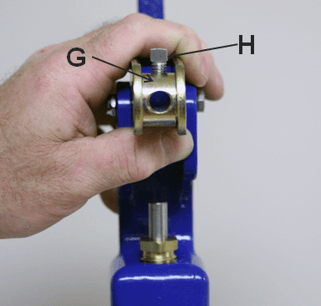
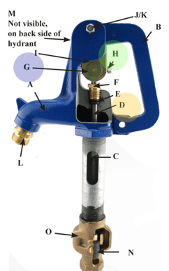
The rubber plunger (Due north) in the lesser of the hydrant can be lowered past raising the point of contact of the square head gear up screw (H) on the S.S. operating rod (D)
Using a 5/16" wrench, loosen the square head bolt so the handle tin can exist moved upwards and down freely without moving the operating rod.
Step 2 & 3
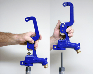
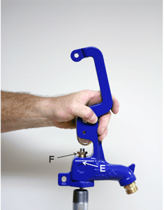
Lift the handle (B) to the fully open position. 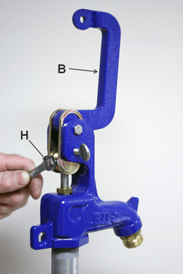
With the handle (B) up in the fully open position, tighten the foursquare head bolt (H)
Step four
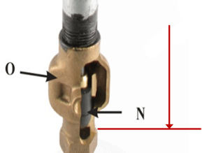
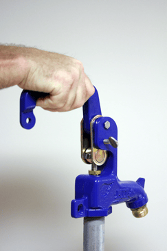 Employ endmost pressure on the handle - this will force the operating rod to assembly / plunger (N) down-wards until it makes contact with the valve seat in the valve trunk (O). Practise non force the handle down -when the handle stops moving you take positioned the plunger against the valve body seat. STOP!
Pace v
 5a - Fix the endmost force per unit area – To do so you must loosen the square head bolt once more, allowing the handle to be moved upwardly and down freely without moving the operating rod. – Do NOT MOVE THE OPERATING ROD FROM POSITION IN STEP #4
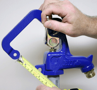
5b- Position the handle then that there is approx. 2" between the handle and the locking tab on the head casting.
Then using a five/16" wrench, tighten the square head commodities so the handle will force the operating rod downwards and apply pressure to close the handle.
Yard Hydrant is Leaking at the Stem Packing
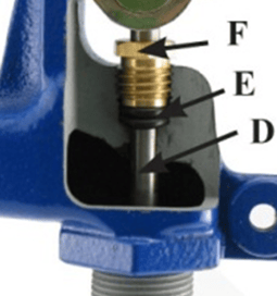
 The brass packing nut (F) has been manufactory adjusted. If leakage does occur it can be easily stopped with a slight adjustment to further compress the double O-Ring seal packing.
Pace #SPA-i
Simply tighten the brass packing nut (F) past turning it clockwise in very small increments until the leakage stops using a ¾" open end wrench.
Caution: DO NOT over tighten packing nut. Excessive pinch will outcome in accelerated wear and or possibly damage to the O-Rings.
Replacement of K Hydrant Head
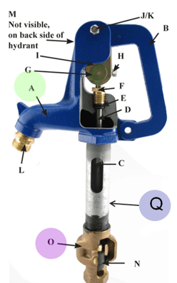 Sometimes, the hydrant head (A) must exist removed due to damages or to replace the plunger (Due north).
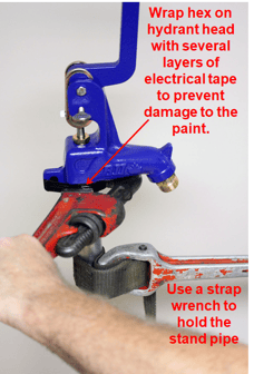
Do not place a pipe wrench on the galvanized stand pipe (Q), information technology will cause harm to the manufacturing plant coating. To forbid the galvanized stand pipe (Q) from turning, use a strap wrench; this should also be followed if tightening the valve body (O).
It is VERY important that the first two steps be followed advisedly to avoid the potential for serious complications.
Failure to do so could upshot in the plunger un-threading from the connecting rod which could exist difficult to re-assemble, perchance resulting in the demand to dig up the hydrant unnecessarily.
Step 1
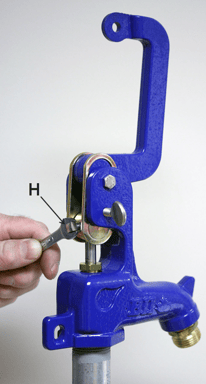 Loosen the v/sixteen"-18 UNC x ¾" xviii.viii Stainless Steel Fix Spiral (H) to let the 3/8" stainless steel operation rod (D) to turn freely in the zinc plated pivot connector (G)
Step 2
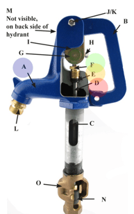 Loosen the ¾" brass packing nut (F) until information technology is not putting any pressure on the O-Ring seals (E) it is meliorate to turn it out completely than to have pressure level on the O-Rings which could issue in the operating rod turning with the head casting (A) loosening the packing nut allows the iii/viii" stainless steel operation rod (D) to turn freely from the head casting (A)
Step 3
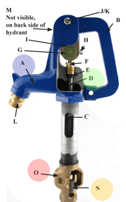 Remove the caput casting (assembly) (A) by turning the head casting counter clockwise (lefty loosey) using a pipage wrench.
Warning!
Make sure to monitor the 3/8" stainless steel operating rod (D) while turning the head casting off the pipe thread. The rod MUST Not turn! If the rod turns it could unthread the connecting rod from the plunger (N) due to the snug fit in the valve body (O)
TIP! – identify a cloth or soft leather or prophylactic sheet between the pipe wrench jaws and the head casting to prevent damage to the corrosion resistant protective paint blanket.
Pace iv
When the head casting (A) is free from the Galvanized stand pipe (Q) approx. 3 – 4 total revolutions, pull the head casting straight up.
At this signal, you would be able to fix any impairment within the hydrant or fully replace the caput.
Step 5
 Brand sure the 5/16"-18 UNC x ¾" 18.8 Stainless Steel Set Spiral (H) is turned out to let the 3/8" stainless steel operating rod (D) to slide freely thru the zinc plated pin connector (Yard)
Step 6
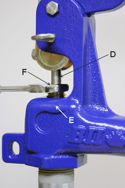 Make sure the ¾" brass packing nut (F) is loose and is not putting whatsoever pressure on the O-ring seals (E) to permit the 3/8" stainless steel operation rod (D) to slide freely thru the O-rings (Due east)
Step vii
 Lower the head casting downwards and then the 3/8" stainless steel performance rod (D) slides thru the O-ring seals (E) and the ¾" brass packing nut (F) and thru zinc plated pivot connector (Yard)
Step 8
 When the head casting (A) touching the Galvanized stand up pipe (Q) apply P.T.F.E. (aka: Teflon) tape or pipe thread sealing chemical compound to the pipe threads, turn the caput casting clockwise engaging the threads making sure that they starting time freely by hand. Tighten using a pipage wrench (righty tightly) approx. 3 – 4 full revolutions until head casting is secure. NO NOT OVERTIGHTEN!
Stride 9
 Tighten the ¾" brass packing nut (F) until it is putting force per unit area on the O-band seals (E) often paw tight is enough Annotation: it takes very petty compression to make a positive seal.
WARNING!
Over tightening of the packing nut tin cause premature clothing and damage to the O-ring seals. Information technology is best to hand tighten at showtime and tighten further in small increments equally required until whatever leakage is stopped when the h2o force per unit area is turned dorsum on.
Step 10
 Adjust the hydrant setting following steps covered in "How do I adjust the hydrant if it has a drip or volition not close off completely?"
When aligning is complete tighten the five/xvi"-18 UNC x ¾" eighteen.eight Stainless Steel Gear up Screw (H) securely to the 3/8" stainless steel performance rod (D) in the zinc plated pivot connector (Thousand) to foreclose slippage of the rod in the pivot connector which would issue in the loss of the hydrant setting. Note: The specially cupped set screw (H) grips very well on the rod so with moderate tightening of the set screw should be sufficient.
Do not leave hose fastened to hose bib in freezing temperatures as information technology may forestall proper drainage of the shut-off valve.
If hose is attached to the hose bib of the hydrant when the hydrant is shut-off, dorsum siphoning can occur if end of hose is left in container of liquid. The end of the hose must be left open up to the air so hydrant can drain back. A back catamenia prevent should be installed if a hose is left on during the warm summertime season.
Replacing the Yard Hydrant Plunger
Step 1
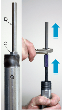 With the head casting removed the hydrant caput casting removed, the S.S. operating rod (D) volition exist protruding out of the galvanized stand pipage (Q) approx. iii-1/2"
Pull the S.South. operating rod (D), coupling [C] connectedness rod [R] and plunger assembly straight up.
NEVER TWIST COUNTER CLOCKWISE, THIS COULD CAUSE THE PLUNGER TO UNTHREAD FROM THE ROD.
Footstep 2
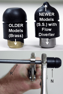 Grip the steel connection rod "R" with a vice grips simply above the plunger (N), with a second vice grip securely grip the brass insert on the plunger associates (stainless steel on newer models), then plow the plunger counter clockwise approx. 7-1/two to 8 turns (nigh ½" thread) to unthread the plunger from the rod.
Step 3
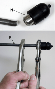 Go on the grip the rod "R" with a vice grips just in a higher place the plunger, with the 2nd vice grip the stainless steel insert on the new plunger (Due north) securely and turn the plunger clockwise to thread information technology onto the rod.
Tighten securely.
Pace iv
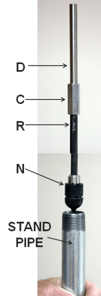 Remove both vice grips, and carefully lower the entire rod and plunger associates (Southward.S. operating rod (D), coupling ©, connecting rod ® and plunger assembly (North)) straight downwards in the stand up pipe until the plunger is pressed into the valve trunk (O) against the valve seat.
NEVER TWIST THE Assembly COUNTER CLOCKWISE, THIS COULD CAUSE THE PLUNGER TO UNTHREAD FROM THE ROD!
After this is consummate, refer dorsum to the Yard Hydrant Head installation instructions. This shows how to install the existing or a new head.
Have further questions almost this subject field?

Head over to Boshart's Knowledge Base: technical production information, guidelines, and more.

How To Repair In Ground Freeze Proof Hydrant,
Source: https://blog.boshart.com/how-to-adjust-and-repair-a-boshart-yard-hydrant
Posted by: meyerdencen1959.blogspot.com
0 Response to "How To Repair In Ground Freeze Proof Hydrant"
Post a Comment